Basically jack climb up on the jack rod
(Part of the lifting trestle) with the desired pressure, to lift up the
load. Its action is same as a monkey that climbs a trunk tree; i.e, first it
holds up on to the trunk with its legs and lunges upwards, then it holds on
to the trunk with its hands and lifts its legs up. At any time, either its
hands or legs have a grip on the trunk, which prevents it from falling down.
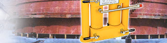
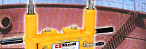
In the same manner, air hydraulic jack, air hydraulic bottle jack and jack
is provided with two pairs of jaws, a lower pair of jaws and an upper pair
of jaws for an excellent grip. During lifting, both the pairs are "locked".
In this position the jack can only move upwards. At the time of lifting, the
lower pair of jaws grip the trestle rod while the jack lifts up. After
completing the full stroke, the upper pair of jaws grip the trestle rod,
however, the base of the jack moves upward. During the process of lowering,
any one of the pairs is always locked.
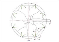
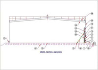
The following description provides a
brief outline about the working procedure of air hydraulic jack and air
hydraulic bottle jack. However, improvements can be certainly done if
required. (Refer the drawing below to develop better understanding).
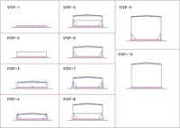
The tank bottom-plates are placed
on the prepared foundation and welded together.
- Spacers cum guide beams of maximum 400 mm height are tack welded
to the tank bottom along the periphery. The plates of the first
shell ring (in fact the top ring of the tank) are positioned and
welded together.
- The lifting equipment is assembled by following a standard
method. The plates of the second shell ring (next to top ring) are
positioned outside the first one.
- The beams or lattice work of the roof are assembled and finally
joined to the upper rim of the shell ring. Inner sheets of the roof
are placed and welded together.
- The completed part of the tank (the roof and top shell ring) is
lifted hydraulically to a height, at which the plates of the second
shell ring can be moved into place and the roof sheeting can be
completed, except for about 2 or 3 roof plates which shall not be
fixed until completion of the tank for air to pass through
- The entire tank is lowered down to the bottom plates and welded
to this. The lifting equipment is dismantled.
- The plates of the third shell ring are placed outside the second
shell ring.
- The completed part of the tank (the roof and the two uppermost
shell rings) is lifted.
- The above cycle of operations is repeated until the last (bottom)
shell ring is finished.
- The plates of the second shell ring are located exactly and
welded together to the lower edge of the first shell ring.
|